Transverter for 4 meters band
( 70 MHz / 145 MHz )
Introduction: In Moldova, the activity is not permitted in the radio band of 70 MHz, as there are several radio stations broadcast at frequencies 66-73 MHz. But I was interested to develop and build their own hands, is what I have not found a description on the Web. So I decided to make a transverter on a range of 70 MHz, in the hope that there ever moldavian hams allowed to use these frequencies.
With access to the transceiver KENWOOD TR-751A (144 - 146 MHz), which was already prepared to work with the transverter DB6NT 5.6 and 10 GHz, ie, output power is reduced to 1 watt, and transfer to the central core of coaxial transmission appears + 12 volts, I decided it was under him and make up to 70 MHz transverter.
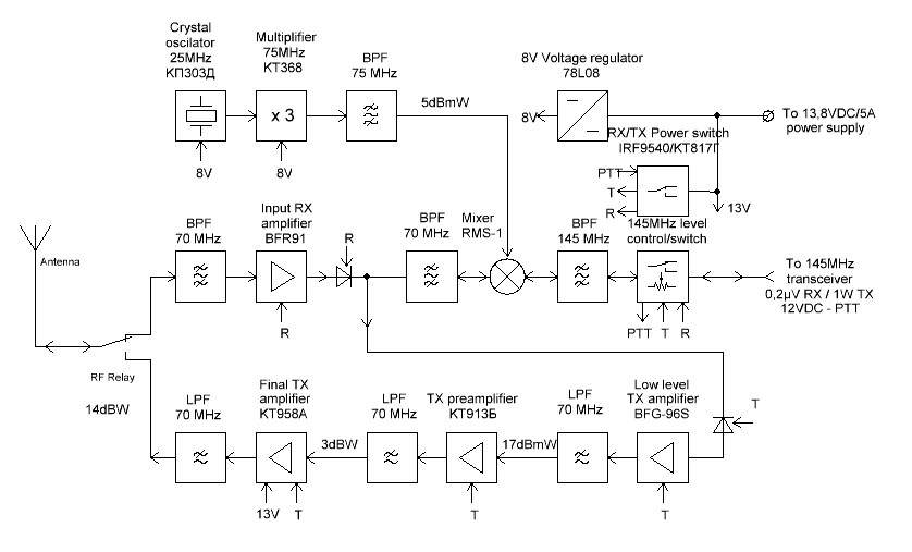
Block diagram of the transverter shown in the figure located in the following, where I tried to define in detail what the active element is used for what. Also shown in this figure reached my level of useful signal.
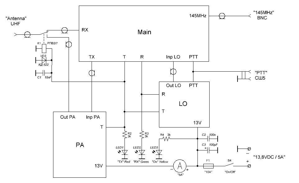
The scheme of connection blocks.
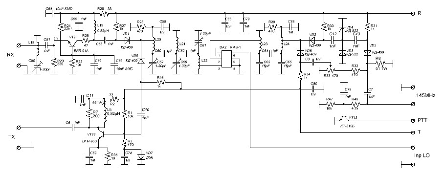
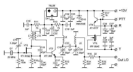
Scheme of the "Main" unit.
Scheme of the crystal oscillator circuit and the switching voltages TX / RX - "LO".
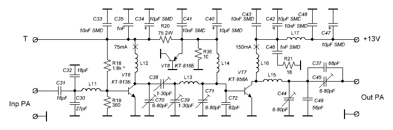
The scheme of the transmitter power amplifier "PA". Initially, I wanted to do a power amplifier using module MITSUBISHI RA30H0608M, but having in the presence of a large number of high-power microwave transistors Soviet-made, I got an interesting design, assemble and adjust the amplifier is shown in the diagram on the elements. Tinkered with every denomination scheme.
25 watts is enough for local and Es QSO's why I did not try to get more power.
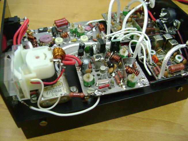
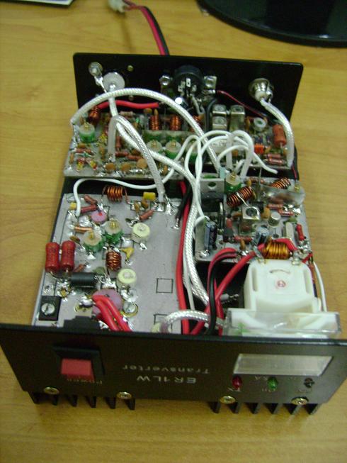
Construction. The basis for the boxes, as well as cooler, finned heat sink is HS115-150, bought by me here. It was convenient because it already has holes for mounting the front and back panels. All parts, except for the indicator, power button, LEDs, relays, and an antenna connector, assembled on three printed circuit boards. Fees blocks "LO" and "Main" mounted above the radiator on the rack height of 5 mm.
Details and winding products. Most denominations used parts, specified in the above schemes. One of the problems in the design of this design was the use of those components, which "are at hand". Purchased items were assumed to be only on the condition that they are either facilitate or simplify a very, or decorate, etc. construction.
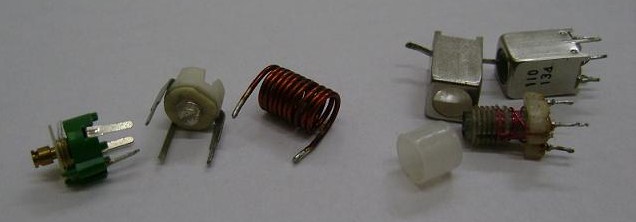
L23 and L24 coils are taken from the receiving channel radio DRAGON SY-252N, but they can make and myself, 2 + 2 turns on the frame 5 mm in diameter with a core of ferrite. The picture detail frame with a screen that shows the right. At the same pictures you can see the variable capacitors are applied by me, because I do not know their type. Green is 1-30 pF capacitor, and white - 6-80 pF.
Coil L8, L9, L18, L20, L21, L22 are wound with 10 turns and wire diameter of 0.8 mm mandrel diameter of 5 mm, with winding length of 12 mm. Removal of some of these coils is made of 3, starting from the output of the RF grounding, turn. The coils L12, L13 and L15 are wound the same as the previous coil wire on the same mandrel, and are 7, 5 and 3 turns. Between the coils L8 and L9 a screen made ??of tinned steel. From the same plate screens are made of coils L20 - L22,
excluding the inductive coupling between the coils and other elements of the scheme. Coils and chokes included in the block "PA", and preferably all other parts of this unit should be pressed as close as possible to the board, eliminating the possibility of self-excitation of the block.
Tuning. Setup begins by checking transverter operation of the circuit RX / TX. Closing the contacts "PTT", check the appearance of voltage + 12 V at the outputs of "T" and "R" block "LO", the translation transverter mode transmission and reception, respectively. Then set the voltage on the findings of transistor dc mentioned in the scheme. Short the crystal constant capacitor capacitance 10nF and connecting to the lower frequency of the scheme concluded coil L10, twist core coils L7, L10 until the frequency meter readings will not be equal to approximately 25 MHz. After that, disconnect the capacitor shorting crystal. Following the frequency of which should be in the range of 75 MHz,
adjust capacitors C18 and C20 trying to get the maximum voltage at the output of LO (contacts "Out LO"). The next step is the selection of the nominal value of resistors R14-R16 and the core is rotating coil L7, the voltage specified in the block diagram transverter. After that the capacitor C73 produces frequency fit as close to 75,000,000 Hz.
Next transverter setup are in receive mode. Submitting to the antenna connector transverter frequency of 70 100 kHz signal and configuring the transceiver to the 145 100 kHz, producing adjustment, first-cored coils L23, L24, and then the capacitors C50, C57, C59 and C61, the maximum signal at the output of LF radio. After that, convert the transceiver is configured to 145 100 kHz and modulation type FM
in the transmission mode, adjust kontensatory C38, C39, C44, C45, C70 and C71, trying to get to the equivalent of a coaxial antenna with a maximum voltage.
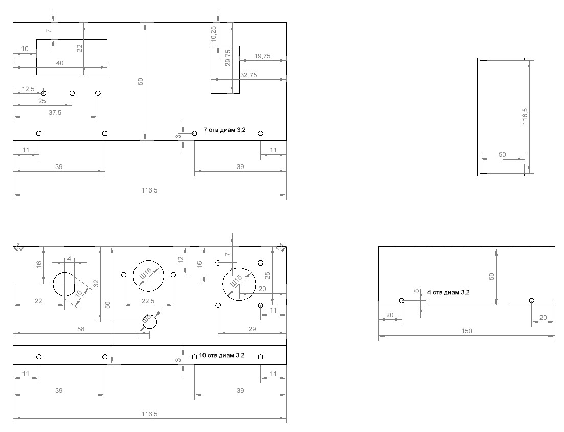
Dimensions of front, rear and bottom covers transverter:
Location blocks transverter: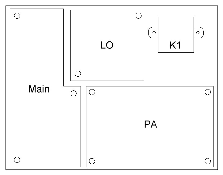
Marking the holes on the radiator transverter: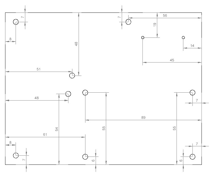
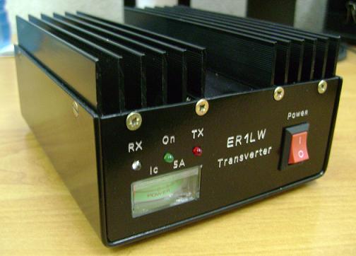
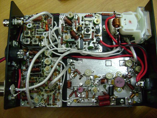
Picture the assembled transverter: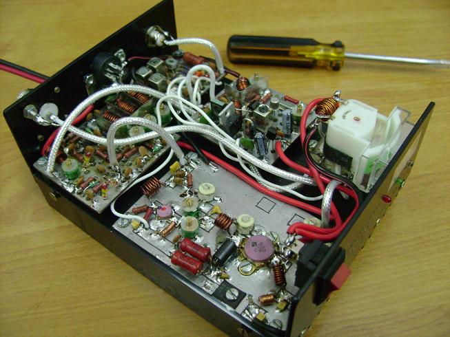
I would be grateful for pointing out all committed in the publication of that material errors and try to rectify as quickly as possible. 73! See you in the air. Slawa / ER1LW
Return to the main page ER1LW in Russian
(c) 2011 - ER1LW