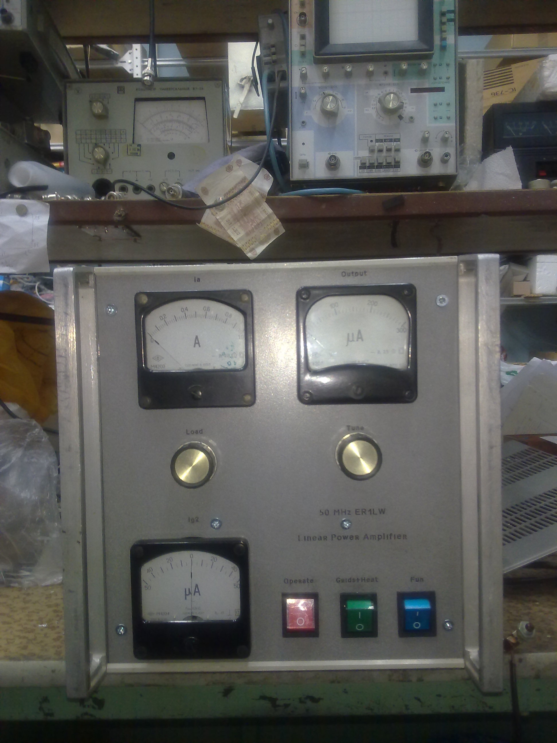
The power amplifier 6-meter band tetrode
GU-43B / 4CX1000 - 1250 W
Introduction:
The amplifier was designed for a QSO using EME, TEP and multiskip Es.
Features tube GU-43B
For many years for DX & Contest QSO on HF I used GU43B tube amplifier, and it was very reliable. So I decided at 50 MHz to power on the same tube. For the circuit, switching, and other low-frequency circuit, I used the scheme to his old amp. The overall schematic diagram is shown below:
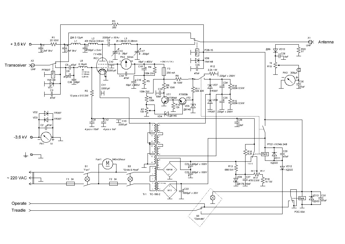
Since the use of powerful tetrode in the grounded-cathode scheme, on its grid must be submitted stabilized voltage, then I made two stabilizers, one on the zener VD9, second transistors VT1 and VT2.
Circuit C5, C6, C36 and L8 is needed in order to compensate for the input capacitance of the tube ( 90 pF ).
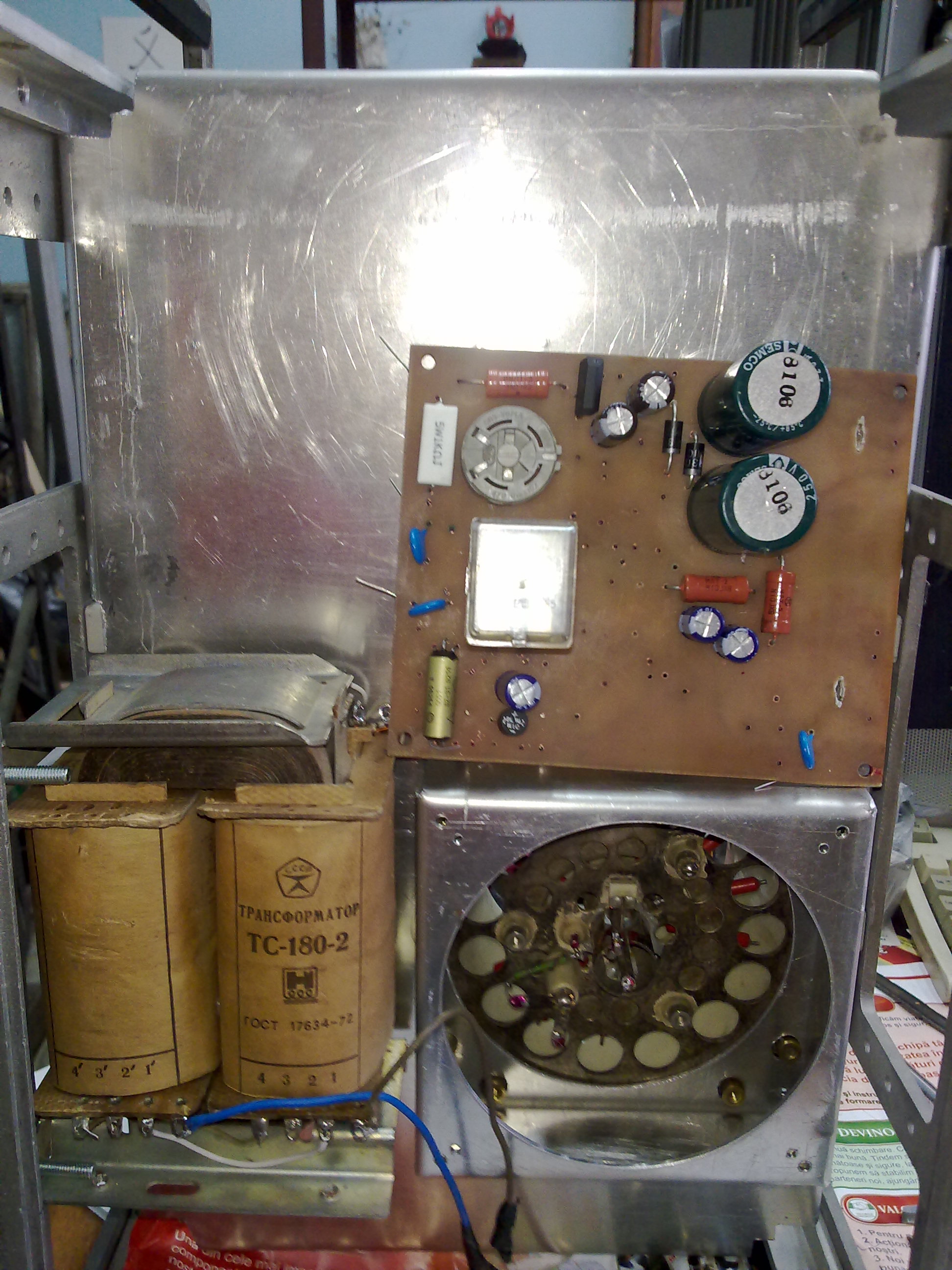
To get all the necessary voltage from AC 220 volts, the transformer has been used from the old Soviet TV.
Construction.
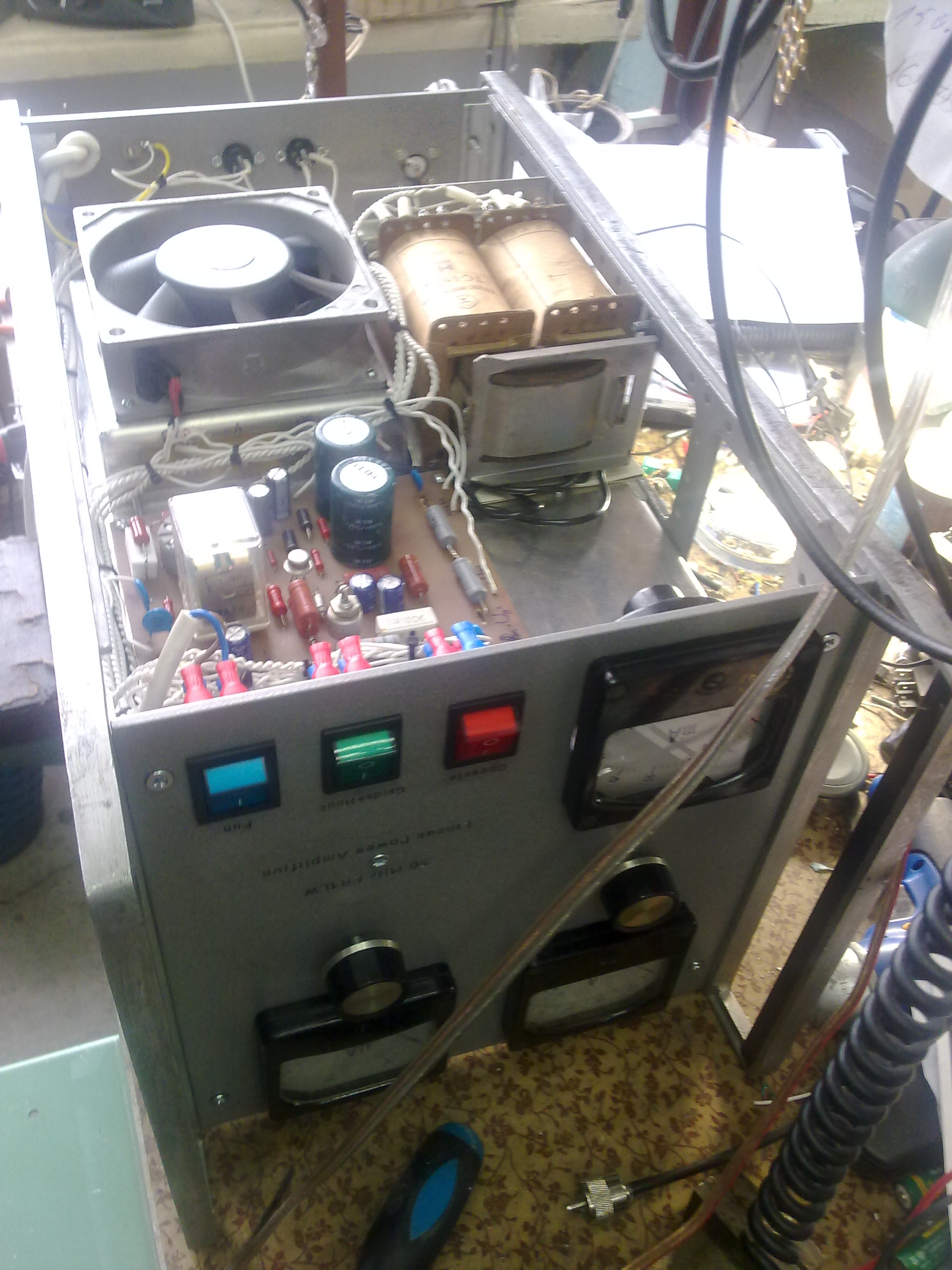
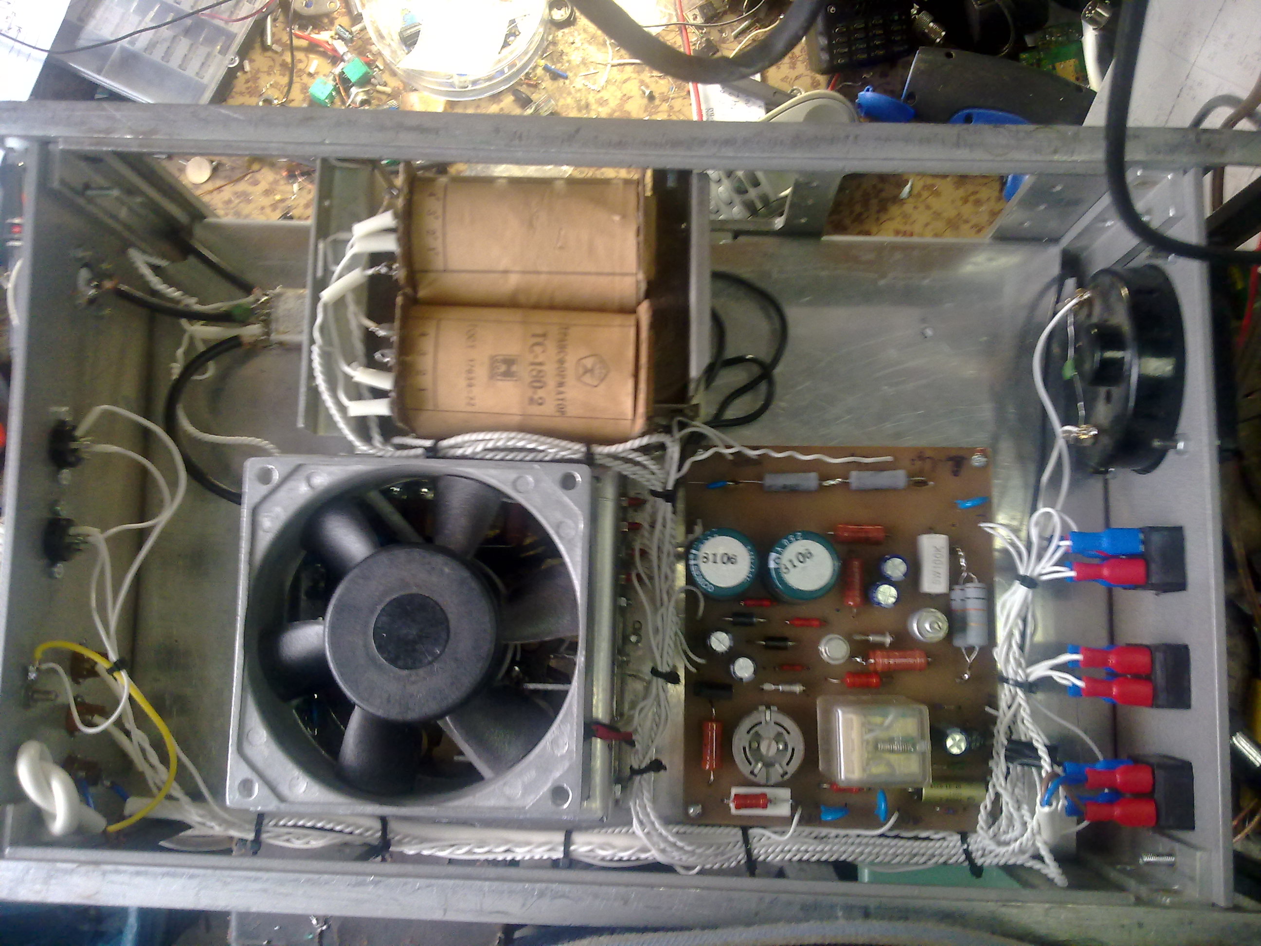
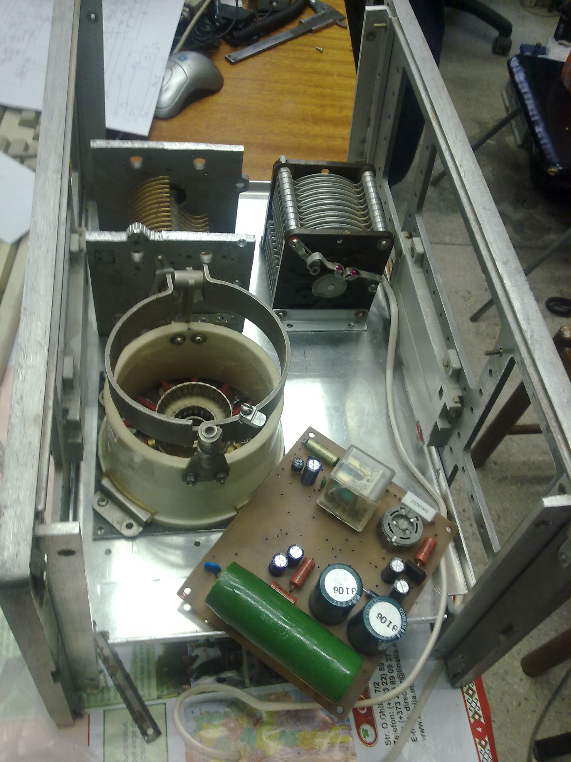
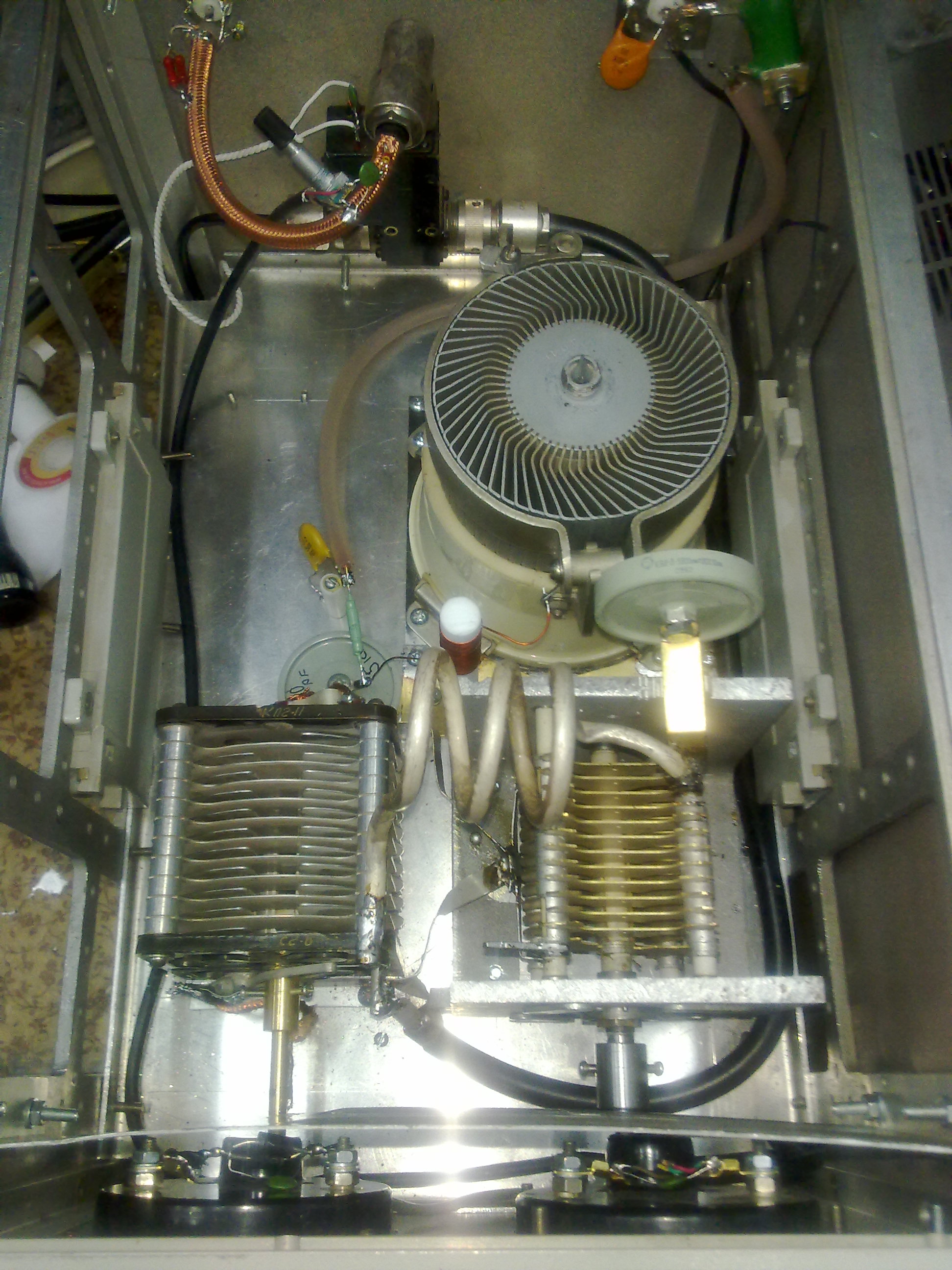
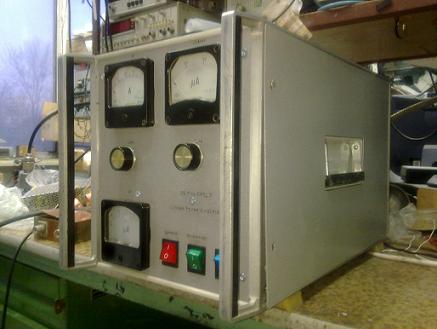
The basis for the amplifier housing building served by the failed old appliance P6-31. Since the in my "shack" quite a few places, I decided to cut it, shortening the width, and now its dimensions are 280 x 260 x 450 mm. The inner space of the body is divided into two parts tray of 2 mm aluminum. From the bottom of the cover is mounted on a pallet height of 90 mm, dividing the space in the building at the top and
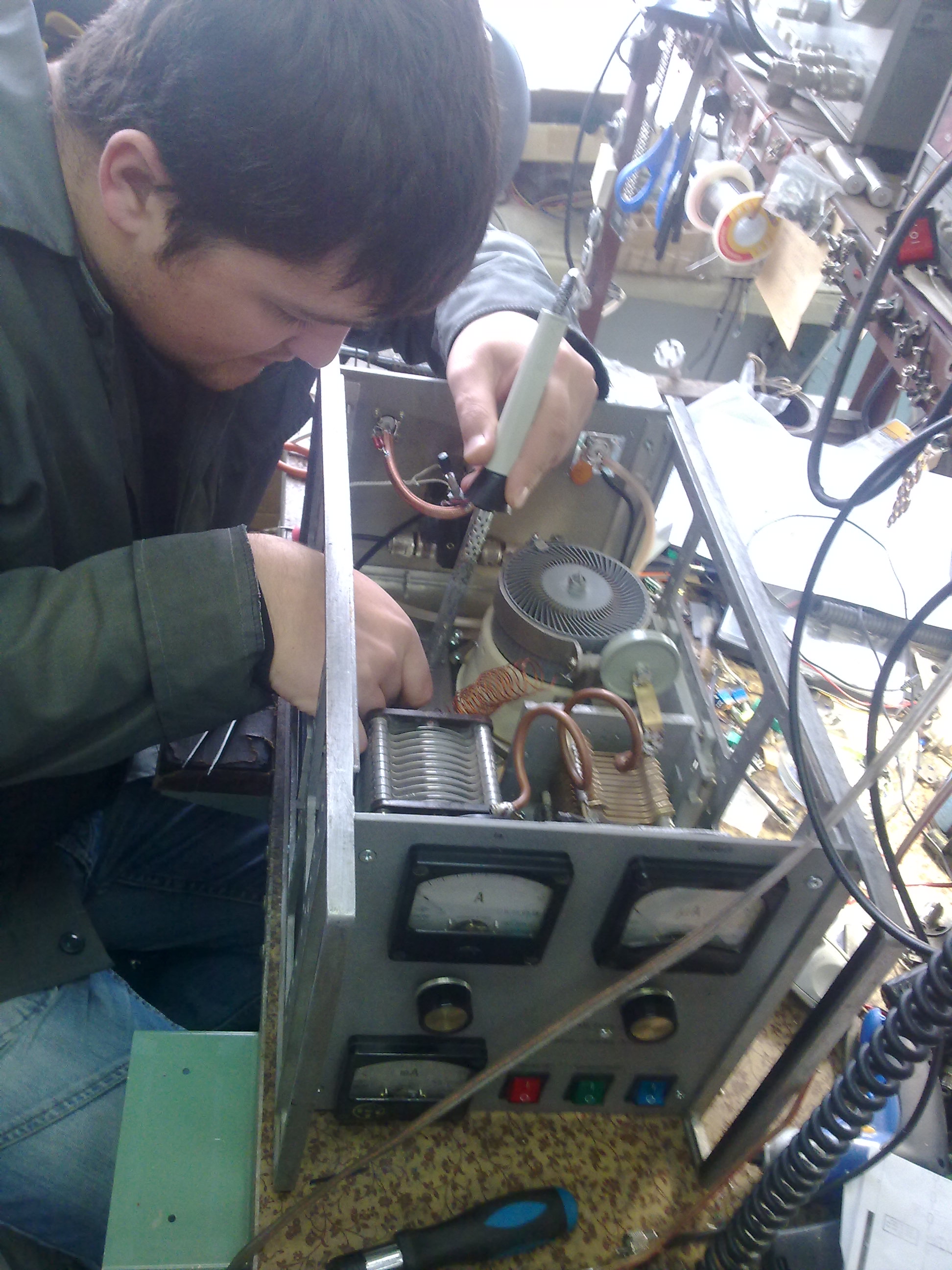
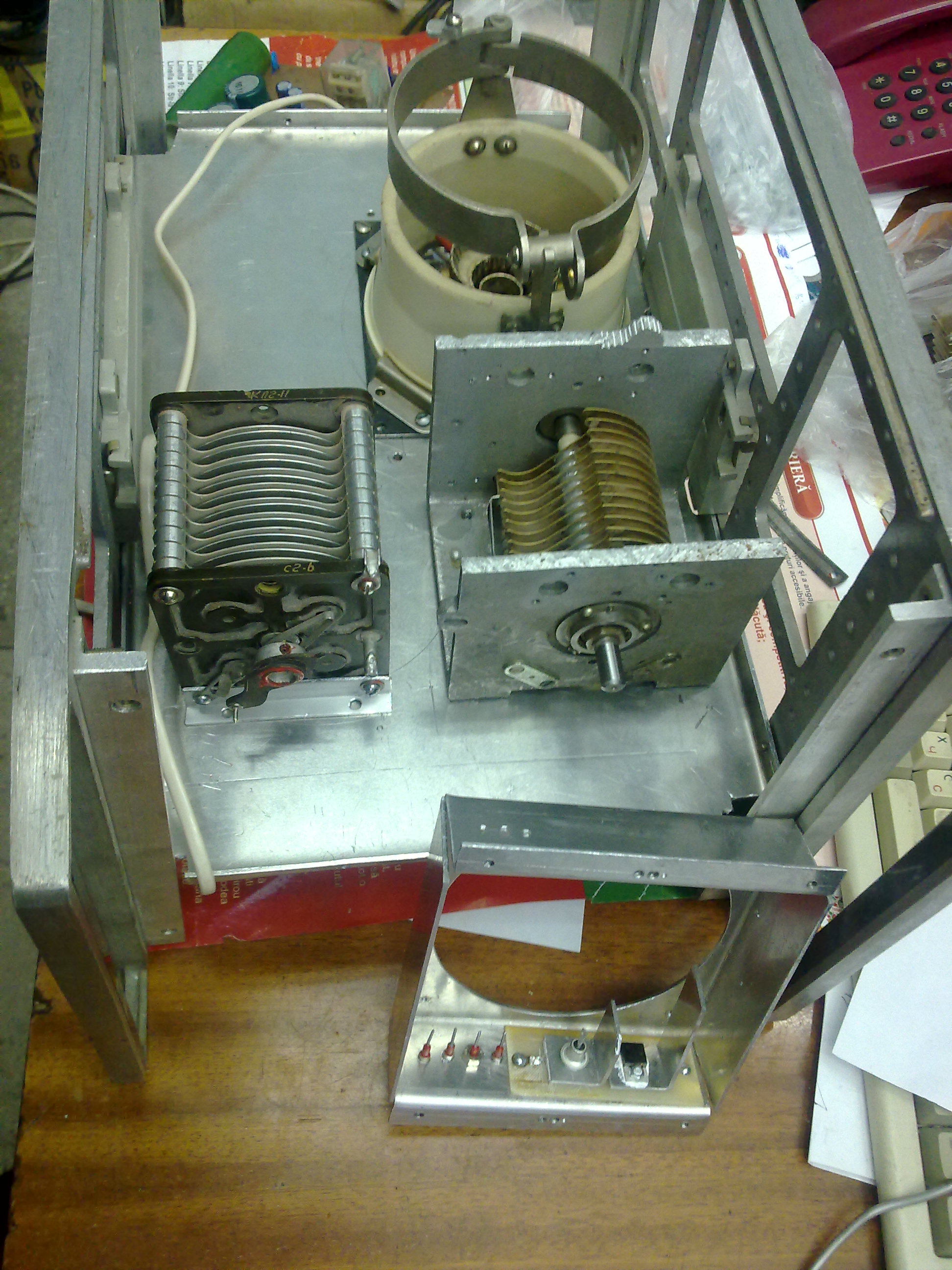
the lower part. The upper part is light, the details of the P-scheme, anode chokes and output relay.
Under the tray are transformer to power grids and heated tetrode, the board with rectifiers, stabilizers and control circuit, the input switches, as well as a basement for a lamp, also made of aluminum, 2 mm thick. In the basement of a tetrode, which pumps air blower with a capacity of 240 cubic meters / hour, are the input resistor 51 ohm, consisting of 10 pcs with capacity of 2 watt resistor. Also in the basement of the tetrode, under a stream of forced air, the radiators are a powerful regulator zener diode screen grid and the output transistor of the stabilizer on-screen grid.
The amplifier circuit, and
well as the size of some parts made me to order,
presented in the format of the program sPlan7.0, you can download here.
Most denominations used parts, specified in the above schemes. One of the problems in the design of this design was to use those components that are available. That's why I do not know the variable types of capacitors and what radio stations they were
withdrawn because it happened about 20 years ago. But even in this case I had to finish off both the condenser, removing superfluous or adding an element mounting, so I think that you can use any capacitors. The main thing that would be the distance between their plates to ensure the absence of high-voltage breakdown and all contact connections kept him on the current high-frequency currents, taking into account the loaded Q of the circuit.
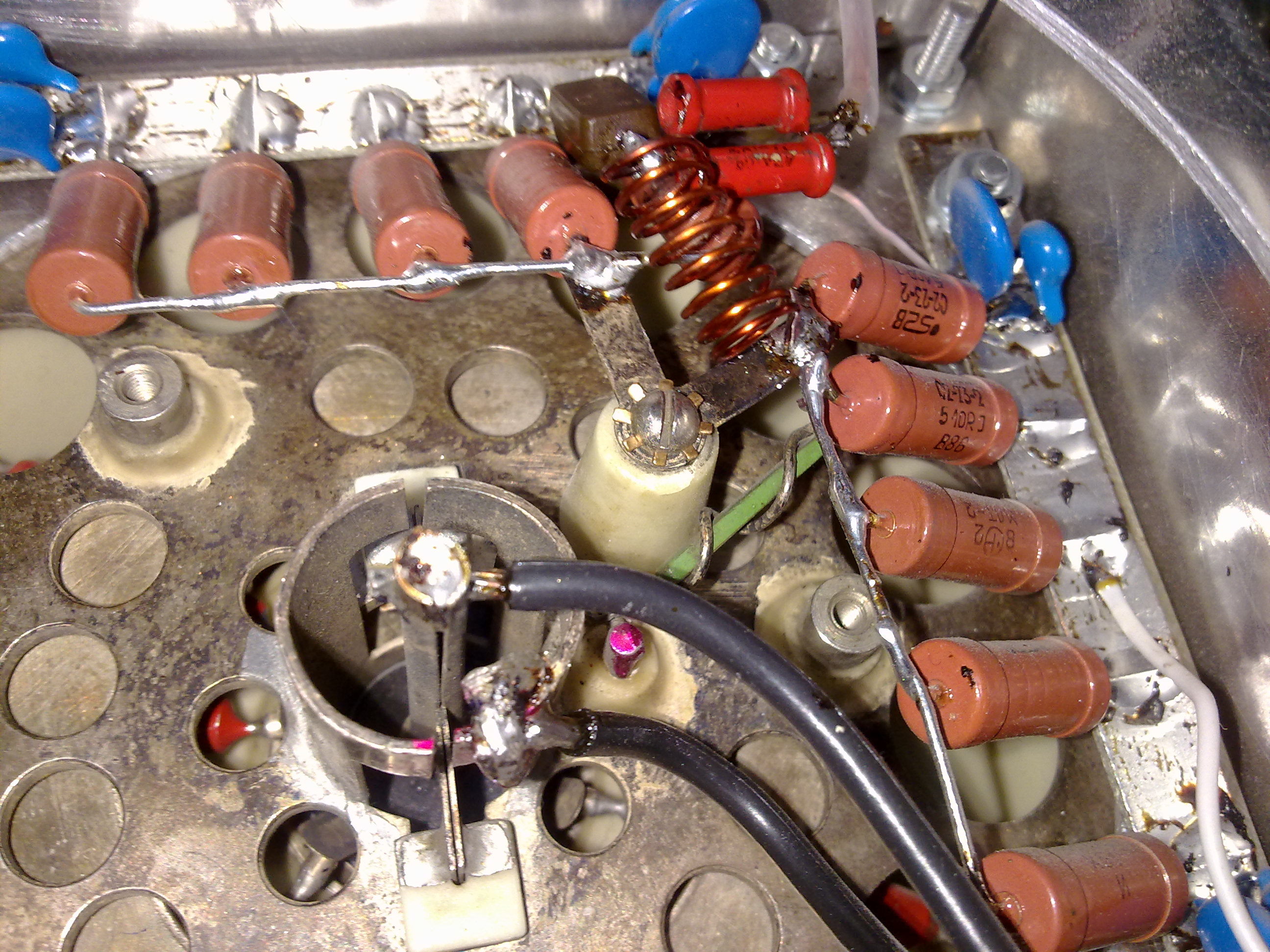
To perform the above decision was taken as the anode C13, use a capacitor-type "butterfly" insulated from the axis of the rotor. Doubled the gap and there are no rubbing contacts for which a large current flows.
When assembling the amplifier should not be forgotten that in some parts, especially the anode supply chains, there are very high voltage potential, so take all the careful steps to isolate and protect against the breakdown in these places. Also do not forget that the elements of the output P-scheme reactive currents flowing tremendous values as high as 10-20 Amper.
For this reason, all connections to the P-scheme to do the shortest, reliable. All contacts should be grounded to connect with each other, short, thick tire.
Setting up the amplifier.
Resistor R7 expose the on-screen grid of the tube voltage of 350 V. A resistor R17 exhibit quiescent current in the range of 300 mA, at which the maximum linearity of the amplifier.
I easily achieved the output power amplifier 1250 watts at 0.65 amperes of anode current and anode voltage of 3200 volts. I reached and the current of 0.8 A, but the power at that time is not measured.
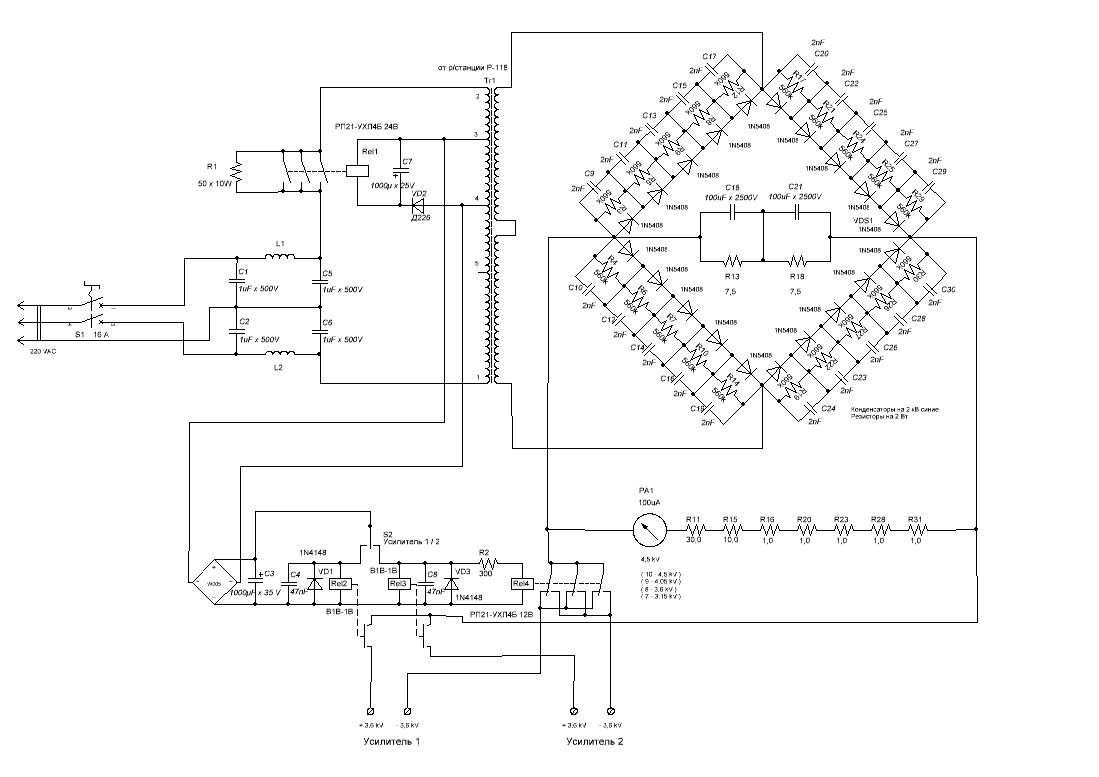
Scheme of power supply. The transformer for the anode voltage is taken from the old military radio station R-118. At Rel1 assembled unit delay submission of full AC voltage on the high-voltage diode rectifier bridge, a switch Rel2-Rel4 switch outputs the power source, as I have it is used to power two amplifiers in the GU-43b.
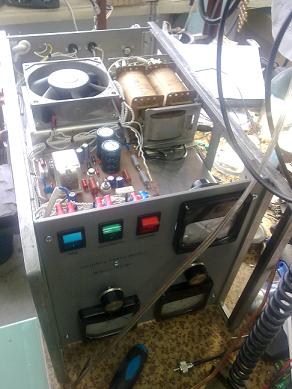
Photos of the amplifier: ( click photo to enlarge )
I helped to design this amplifier Ivan Ursu, Grigorii Login and other hams, for which I express my gratitude to them.
My signals in Japan using PA on GU-43B in 2 jul 2012http://youtu.be/K5bVntzNBto
73! I hope to meet up to 50 MHz. Slawa / ER1LW
Return to the home page ER1LW in Russian
(c) 2012 - ER1LW